2.5.3. Alignment elements
2.5.3.1. Horizontal alignment elements
Internally a horizontal alignment is a chain of four primitive
element types: Line, Arc, Clothoid spiral and Cubic
parabola spiral. Each element exposes a common interface — start
point, start direction, length, end point, end direction, point at
distance, direction at distance, curvature at distance — and the
chain accumulates them into a continuous, raw-distance parameterised
centreline. The displayed station value is then RawToStation(raw)
which applies the Start Station offset and any station
equations defined on the geometry.
The sign convention used everywhere:
Curvature
k = dψ/ds(rate of heading change with arc length). Left turn (counter-clockwise) ⇒k > 0.Offset: positive = right of travel, negative = left.
Bearing: the project’s angular units (degrees / gradians) measured from North, increasing clockwise — exactly as you would read on a total-station compass.
2.5.3.1.1. Line
The simplest segment — a straight line of length
L = ‖(End − Start)‖ between two end-points with a constant
direction ψ = ArcTan2(ΔY, ΔX).
Field |
Description |
Start X |
Easting of the start point |
Start Y |
Northing of the start point |
End X |
Easting of the end point |
End Y |
Northing of the end point |
Start Sta |
Station value at the start point |
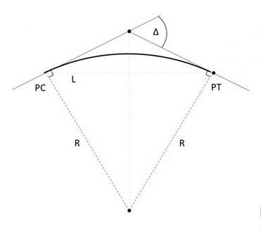
2.5.3.1.2. Arc (circular)
A circular arc of constant radius R, defined by a centre point
(cx, cy), a starting direction and a length. The internal
representation uses signed curvature so that the same data type
covers both turn directions:
with k > 0 for a true left turn (CCW) and k < 0 for a right
turn (CW). The Clockwise flag stored on each arc element drives the
sweep direction at draw time.
Field |
Description |
Center X |
Easting of the centre point |
Center Y |
Northing of the centre point |
Bearing |
Bearing of the start tangent (gradians) |
Start Sta |
Station value at the start point |
Length |
Arc length |
Radius |
Signed: |
Note
The legacy TCML / ALM <HElement> import format encodes the arc
turn with a signed Radius attribute. Some exporters use the
opposite sign convention; the current version derives turn
direction from geometry (continuity with the previous element’s
end direction) rather than the radius sign, so files from either
convention round-trip correctly.
2.5.3.1.3. Clothoid spiral
A clothoid (Euler spiral, Cornu spiral) is the transition curve whose curvature varies linearly with arc length:
where A is the clothoid parameter. The signature property
A² = R · L is exactly what makes the curve so useful in roads
and railways: the transverse acceleration on a vehicle at speed
v is v² · k(s), and a clothoid distributes the change of
acceleration at a constant rate — there is no abrupt jerk where
a tangent meets an arc. Highways and rail lines therefore use a
clothoid between any tangent and circular curve (and again between
that curve and the next tangent), to keep the lateral acceleration
profile a continuous ramp.
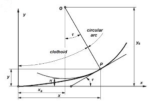
2.5.3.1.3.1. The intrinsic equations
Place the origin at the inflection point (where curvature is zero)
and align the X axis with the local tangent. With K = R · L
(the product radius × length of the spiral, also written
R · L in the editor and in .alm files as RLValue), the
position at a parametric distance D along the spiral is given by
the Fresnel-integral series expansion (kept to the third term, which
is more than enough for civil-engineering distances):
The tangent direction at distance D is
so curvature grows linearly:
k(D) = D / K = D / (R · L) — at D = L we have
k = 1/R and the clothoid meets the circular arc tangentially
without jerk.
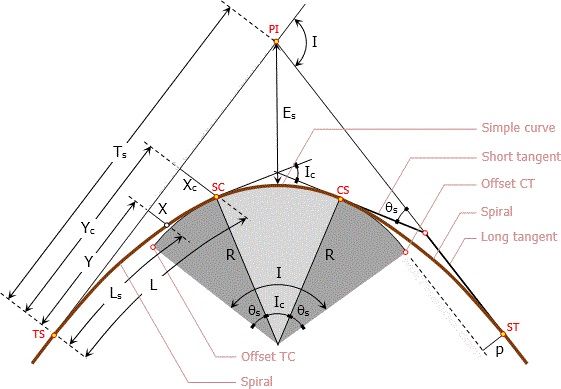
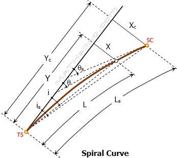
(The .gif versions of these figures in the source tree are
animations that visualise how a vehicle’s lateral acceleration
ramps up linearly along the spiral.)
In the editor a clothoid is described either by its start point /
tangent / length / start radius / end radius, or by its origin
point (the inflection point where curvature is zero) plus the same
length and R·L value. Internally the engine always stores
(start point, start direction, start radius, end radius, length,
clockwise)
and recomputes everything from that minimal description.
2.5.3.1.3.1.1. Defining a clothoid by start point
Field |
Description |
Start X |
Easting of the start point |
Start Y |
Northing of the start point |
Bearing |
Tangent bearing at start (gradians) |
Start Sta |
Station value at the start point |
Length |
Arc length of the spiral |
Start Radius |
|
End Radius |
|
2.5.3.1.3.1.2. Defining a clothoid by origin
Field |
Description |
Origin X |
Easting of the inflection (zero curvature) |
Origin Y |
Northing of the inflection |
Bearing |
Tangent bearing at origin (gradians) |
Sta at Origin |
Station value at the origin |
Length |
Arc length of the spiral |
R · L |
Clothoid parameter (radius × length) |
Start Sta |
Station value at the start point |
2.5.3.1.4. Cubic parabola spiral
The cubic parabola is the spiral classically used by the British, Indian and a number of Commonwealth railway standards as a simpler substitute for the clothoid. It tracks curvature linearly along the chord (rather than along the arc length, as the clothoid does), which produces a small but bounded discrepancy with the true spiral for the modest deflection angles typical in railway practice. For small deflections the two curves are visually indistinguishable.
The position is, in the same intrinsic frame as the clothoid:
That is — directly a cubic in x, rather than the Fresnel-integral
series the clothoid requires. The single relation y = x³/(6K) is
the property that makes the cubic parabola attractive for
slide-rule / table-based field setting-out; the curvature is
which approaches x/K for small x²/K — i.e. for the angles
encountered on a railway curve (≤ ~10°) the cubic parabola behaves as
a clothoid to a few millimetres on a 1 km curve.
When to use which spiral:
Clothoid — modern roads, high-speed rail, all LandXML interchange. Continuous curvature growth
= s/Kexactly.Cubic parabola — heritage railway alignments, certain UK / IR / Australian rail standards.
The cubic-parabola element accepts the same input modes as the
clothoid (by start point or by origin); the engine fits the same
(start, start direction, start radius, end radius, length,
clockwise)
internal representation, then evaluates points and
tangents using the cubic relation above instead of the Fresnel
series.
Field |
Description |
Start X |
Easting of the start point |
Start Y |
Northing of the start point |
Bearing |
Tangent bearing at start (gradians) |
Start Sta |
Station value at the start point |
Length |
Length of the parabolic spiral |
Start Radius |
|
End Radius |
|
Alternative: define by origin, R·L and length, same as the clothoid.
2.5.3.2. Vertical alignment elements
The vertical profile (chainage ➜ elevation) is built from two element families:
Grade: a straight segment of constant slope
g = (h_end − h_start) / (sta_end − sta_start).Vertical curve: a parabolic vertical curve (the highway convention) or a circular vertical curve (the railway convention). Both elements interpolate elevation between two grades; the editor and importers accept both.
2.5.3.2.1. Parabolic vertical curve
The parabolic VC is parameterised by the PVI (point of vertical
intersection) and the curve length L. With incoming grade
g₁ and outgoing grade g₂:
over s ∈ [0, L], with BVC = beginning of vertical curve
(half the length back from the PVI). The convention
R · 100 = L / (g₁ − g₂) defines an equivalent radius used in
some import/export formats (+ convex / crest, − concave /
sag).
2.5.3.2.2. Circular vertical curve
A circular VC is a true circular arc in the (station, elevation)
plane. The engine accepts both forms on import; for typical highway
geometries the two are visually indistinguishable for L ≪ R.
2.5.3.2.3. Profile editor fields
Grade element:
Field |
Description |
Start Height |
Elevation at the start |
Start Station |
Chainage at the start |
End Height |
Elevation at the end |
End Station |
Chainage at the end |
Vertical curve element:
Field |
Description |
Start Height |
Elevation at the start (BVC) |
Start Slope |
Incoming grade (rise/run) |
Start Station |
Station at the BVC |
Length |
Curve length |
Radius |
|
2.5.3.3. Cross-section collections
Each of the following is a list of segments
(startSta, startValue, endSta, endValue), linearly interpolated
between the segment endpoints and held flat outside the defined
range. The editor exposes them as separate grids and they round-trip
in LandXML, ASCII and native .alm.
2.5.3.3.1. Horizontal offset alignment
Defines an offset centreline parallel to the geometric
centreline. Setout(Chainage, Offset, Dh) with Mode = Offset
Axis measures the offset from this offset centreline instead of
the geometric centreline.
Field |
Description |
Start Station |
Start chainage |
Horizontal Off |
Lateral offset value |
End Station |
End chainage |
Horizontal Off |
Lateral offset value |
2.5.3.3.2. Vertical offset alignment
Adds a vertical offset to the profile elevation.
2.5.3.3.3. Superelevation left / right
Cross-fall of the road surface left / right of centreline, expressed
as a percentage of % (positive = outer edge higher). The setout
engine multiplies this with the offset to compute point height
above the alignment elevation.
2.5.3.3.4. Superelevation-offset left / right
Per-station offset to add to the superelevation values (rarely used; provided for full LandXML compatibility).
2.5.3.3.5. Widening left / right
Per-station lateral widening of the road edge (positive widens outward). The editor optionally draws the widened edges on the horizontal plan.
2.5.3.3.6. Cant (rail only)
The rail-bank value (cm) per chainage, used by Mode = Rail setout. The cant is independent of the road super-elevation collections; it represents the height difference between the two rails on a track centreline. See Rail alignment — cant, CTC and UTC for the detailed CTC/UTC geometry that converts (CTC offset, CTC Dh, cant, gauge, rotation point) into the world (X, Y, Z, Theta).