2.5.1. Introduction
Alignment Solver lets civil-engineering and surveying users define a horizontal centreline, a vertical profile and the usual cross-section collections (super-elevation, widening, horizontal/vertical offset axis, transitional offsets, cant), then perform setout, measure, compare and report calculations against that data.
The current version is built on top of the ICAD Civil engine and replaces the older bespoke renderer/format with a unified TAECC-based drawing model. It adds:
a full station-equation system that is honoured everywhere (drawing, setout, measure, report);
3D mode for vertical shafts and steep inclines: chainage along the true 3D axis, with sections perpendicular to it (see 3D mode and vertical shafts);
a GRD point import path that creates AEC points + builds a TIN surface with contours;
a single Setout / Measure dialog with a Mode selector (Centerline / Offset Axis / Rail) that replaces four separate legacy dialogs;
an HTML alignment report (Tools ▸ Alignment Report…);
a modernised alignment editor (Apply auto-solves PIs, the Station-Equations tab uses chainage-based entry);
a comprehensive Results page with right-click popup (Select All / Copy / Delete Selection / Delete All) and tab- delimited output that pastes straight into Excel.
The horizontal alignment is composed of lines, circular arcs, clothoid transitions and cubic parabolas (the four primitives the engine recognises). The vertical alignment is built from grades and parabolic or circular vertical curves. Cross-section data are station-keyed linear interpolations.
2.5.1.1. What you can do
Compute on the alignment
Setout one point — chainage / offset / Dh ➜ X / Y / elevation / bearing / grade / superelevation / turn.
Setout a station range (Batch Setout) — full chainage walk with the same mode selector (Centerline / Offset Axis / Rail).
Setout from a file of (chainage, offset, …) rows; multiple offsets per chainage.
Setout on the rail alignment — produces the detailed CTC / UTC report (cant, theta, gauge, rotation point).
Measure (X, Y, Z) ➜ chainage / offset / elevation / bearing / super-elevation; single point or from file.
Compare a measured world point + bearing against the design.
Run the rail-specific PI solver / build alignment from PIs.
Import
LandXML 1.2 (horizontal + vertical, with
<StaEquation>).Native
.alm(TCML 2.0) — full round-trip including station equations.PIs from
.S01/ vertical PVIs from.S02Greek PSIMO files.GRD point files with automatic TIN surface and contour generation.
ASCII-delimited tables of any alignment sub-collection.
Export
LandXML 1.2 (full round-trip, equations preserved).
Native
.alm(TCML 2.0).Leica GSI (Road Runner), Trimble TGO ASCII, Anadelta, TCP-Tunnel (Aplitop), Amberg GRP, NRG/NST, Bentley Inroads ASCII, Greek PSIMO.
HTML alignment report — Tools ▸ Alignment Report… (browser-ready).
2.5.1.2. Main screen
The application’s main window hosts one tab per loaded alignment. Each tab contains a tree on the left (Horizontal / Vertical / Station Equations / Superelevation / Widenings / Offset / Cant / Rail) with live element counts, a grid in the middle that lists the selected category’s rows, and a Drawing / Profile / Results page notebook on the right.
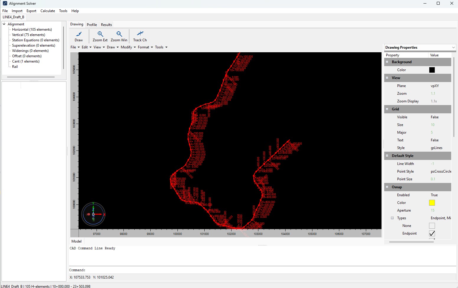
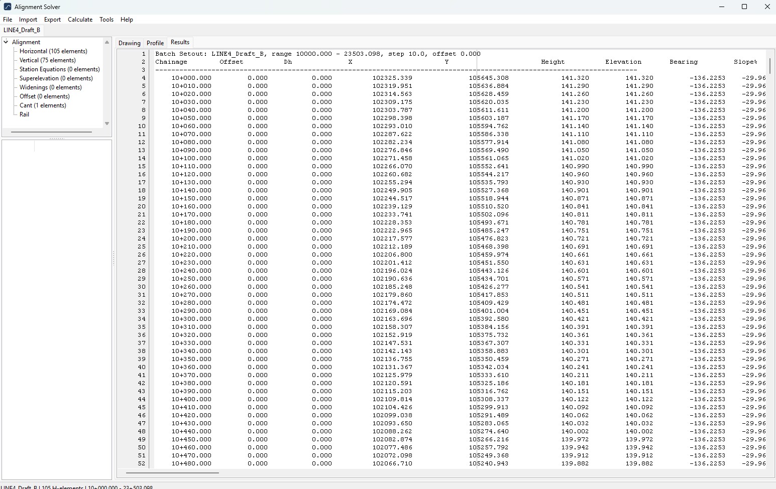
The tree node labels now carry a live count, e.g.
Horizontal (22 elements), Vertical (15 elements),
Station Equations (1 elements), Superelevation (4 elements)…
so the structure of the data is visible at a glance.
2.5.1.3. Where this manual lives
Source in ReStructuredText under manual/source/; build via
sphinx. HTML and PDF outputs land in manual/build/.
Build commands:
pip install -r requirements.pip
cd manual
make html              # -> manual/build/html/
make latexpdf          # -> manual/build/latex/AlignmentSolver.pdf
(LaTeX requires a working TeX distribution — TeX Live full, MiKTeX, or similar.)