2.5.7.1. Setout and Measure
Setout and Measure are inverse operations on the alignment:
Setout takes a chainage + offset (+ optional Dh) and returns a world point
(X, Y, Z)plus bearing / grade / superelevation / turn at that station.Measure takes a world point
(X, Y, Z)and returns the nearest alignment chainage + offset + elevation + bearing / grade at that point.
Both operations live in the same dialog now — Calculate ▸ Setout… or Calculate ▸ Measure… both open the unified Setout/Measure dialog with the appropriate operation preselected.
2.5.7.1.1. Unified Setout / Measure dialog
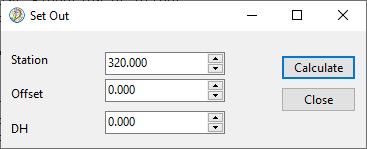
The dialog has two top-level switches:
Operation — Setout (chainage ➜ XY) or Measure (XY ➜ chainage).
Mode — Centerline, Offset Axis, or Rail.
The input fields swap with Operation; the Mode combo selects which engine call is used:
Operation |
Mode |
Engine call |
|---|---|---|
Setout |
Centerline |
|
Setout |
Offset Axis |
|
Setout |
Rail |
|
Measure |
Centerline |
|
Measure |
Offset Axis |
|
Measure |
Rail |
|
When Mode = Rail in Setout, an extra Rail Details panel appears showing CTC / UTC / Cant / Cant Point / Cant Point X-Y / Theta / Gauge inline (see Rail alignment — cant, CTC and UTC).
2.5.7.1.2. Results page
Press Add to Results to append the current row to the Results page. The dialog tracks the kind of row last added; switching Mode (e.g. Centerline → Rail) or Operation (Setout → Measure) and pressing Add to Results again inserts a fresh header for the new table so the Results page stays self-describing.
The Results page itself is a SynEdit with a right-click popup containing:
Select All (Ctrl+A) — select all text;
Copy (Ctrl+C) — copy selection to clipboard (tab-delimited, pastes cleanly into Excel);
Delete Selection (Del) — clear the highlighted text;
Delete All (Ctrl+Del) —
FSession.Results.Clear.
2.5.7.1.3. Setout one point — Centerline / Offset Axis
Inputs: Chainage, Offset, Dh.
Chainage — displayed station value (post station-equation).
Offset — lateral distance from the centreline (Centerline mode) or from the offset axis (Offset Axis mode). Positive = right of travel.
Dh — vertical offset added to the alignment elevation. Defaults to 0.
In 3D mode chainage is the 3D length along the axis, Offset and Dh are measured in the section plane, and the superelevation / turn rows show U / V and R / Theta. See 3D mode and vertical shafts.
Calc returns:
Field |
Description |
X, Y |
World coordinates |
Chainage |
Echo of input |
Offset |
Echo of input |
Height |
|
Elevation |
Alignment elevation at this station |
Bearing |
Travel direction (degrees or grad) |
Slope |
Vertical grade in % |
Super L / R |
Superelevation % |
Turn |
Straight / Left / Right |
2.5.7.1.4. Batch setout — chainage range
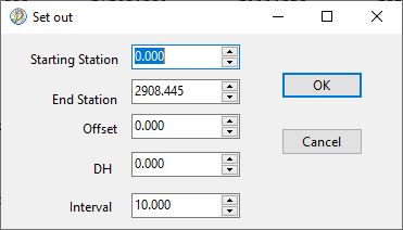
Sweeps chainage from Start to End with a chosen Step, calling the selected mode for each. Rows go straight to the Results page using the appropriate header (Centerline/Offset Axis use the standard report; Rail uses the detailed report — see Rail alignment — cant, CTC and UTC).
Station-equation handling: when an equation defines a forward
gap [Back, Ahead] (Ahead > Back, those chainages don’t exist on
the alignment), Batch Setout skips iterations whose chainage falls
strictly inside the gap. The boundary stations themselves are
emitted (ch = Back and ch = Ahead); both physically refer to
the same point at raw distance rawStation and consequently the
Centerline X / Y / elevation rows for them match exactly.
Sample header row of the centerline report:
Chainage Offset Dh X Y Height Elevation Bearing Slope% SuperL% SuperR% Turn
2.5.7.1.5. Setout from file
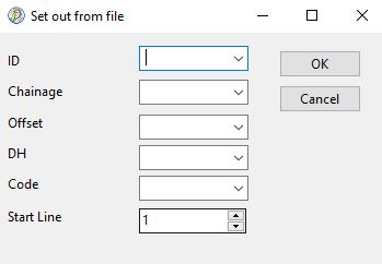
Reads a delimited file of (id, chainage, offset, dh, code) rows
and sets out each one. Minimum required columns are chainage and
offset. The delimiter is set in Options ▸ Input delimiter.
Sample input:
1, 123, 10, 0, pnt1
2, 135, 15, 0, pnt2
The result rows go on the Results page exactly as for single-point setout.
2.5.7.1.6. Multiple offsets from file
Useful for mass-setting-out bridges and roadways at several constant offsets along the same chainage range. The file format is:
offset1, offset2, offset3, ...   <- offsets
dh                                <- one Dh applied to all
chainage                          <- one chainage per row from here
chainage
...
Example:
10, -10, 20, -20
-0.50
300
310
320
The result page lays out all offsets side by side per chainage, with superelevation-corrected heights:
ID    Chainage      DH         X1         Y1         H1         X2         Y2         H2  ...
           Offset            10                                -10
1      300.000    -0.500   17170.684  1355.810   1022.846   17151.506  1350.134   1023.034  ...
2.5.7.1.7. Measure
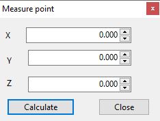
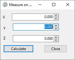
Single point: enter X, Y, Z; the engine reports the nearest chainage + offset + (alignment) elevation + bearing / grade / super.
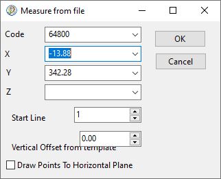
From file: same routine driven by a delimited list of points; the results page collects them.
2.5.7.1.7.1. Measure on offset alignment
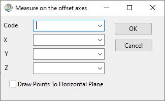
Mode = Offset Axis (in the unified dialog): the engine still measures against the geometric centreline but reports the offset as the distance from the offset axis at the matched chainage (centreline offset minus the horizontal-offset value at that chainage).
2.5.7.1.8. Compare
Measures a world point + bearing against the design and reports station, perpendicular distance, intersection X/Y, design elevation and design grade at the intersection. Used for stake-out QA and surveyor checks.
2.5.7.1.9. Check alignment
Scans for connection errors between elements at horizontal and vertical alignment — gap or overlap between successive elements, direction discontinuities, etc. Reports findings on the Results page.
----------------------------------------------------------------
Check to Horizontal Alignment elements of alignment :test align
----------------------------------------------------------------

There are 0 errors in Horizontal Alignment

---------------------------------------------------
Check to Profile elements of alignment :test align
---------------------------------------------------

There are 0 errors in Profile