2.5.2. Options
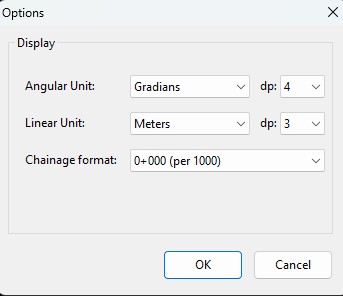
Tools ▸ Options opens a tabbed dialog with General options that apply to the program as a whole, plus per-alignment Alignment Settings (Tools ▸ Alignment Settings…) that travel with each tab.
2.5.2.1. General
2.5.2.1.1. Output delimiter
Sets the delimiter used in the Results page and in delimited file export. Tab is the recommended value — it copies cleanly out of the Results popup (Ctrl+A / Ctrl+C) and pastes into Excel as separate columns.
2.5.2.1.2. Input delimiter
Delimiter expected when reading delimited input files (Setout/Measure-from-file, ASCII import). Accepts comma, tab or space.
2.5.2.1.3. Language
UI language. New translations can be added by dropping a .po /
.mo pair into locale/.
2.5.2.1.4. Decimal places
Number of decimal places shown in computed results (X, Y, elevation, station, etc.). The angular sub-setting caps gradian / degree precision separately.
2.5.2.2. Horizontal — drawing options
Scale — drawing scale for plan view.
Left / Right width — half-widths of the roadway used to draw edges around the centreline.
Draw widenings — overlays the per-station widening on the plan view.
Widening step — chainage interval at which widening edges are sampled.
2.5.2.2.1. Units
Linear units — Meters, US-foot, International foot.
Angular units — Gradians or decimal degrees.
The chosen units flow through every formatted number — chainage
formatting (k+mmm.ddd metric, sta+ft.ddd imperial), bearings,
and the on-window status bar live readout.
2.5.2.3. 3D mode
Use 3D mode (Alignment Settings) stations the alignment along its true 3D axis, with sections perpendicular to it — needed for vertical shafts and steep inclines. Section azimuth orients the section axes of a vertical shaft. See 3D mode and vertical shafts.
2.5.2.4. Rail
When the alignment is flagged as Rail, the rail panel becomes active. The cant table becomes editable, the unified Setout/Measure dialog enables Mode = Rail, and the rail-detailed report format is used.
2.5.2.4.1. Gauge
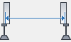
The distance between the two rails of the track, in metres.
Typical values used in production:
1.435 m — Standard / European / North-American gauge.
1.520 m — Russian / former-Soviet gauge.
1.600 m — Irish gauge.
1.668 m — Iberian gauge.
1.067 m (3 ft 6 in) — Cape gauge (South Africa, Japan main lines).
For metro lines the project gauge can be 1.435 m, 1.500 m or other project-specific values. The full rail-setout report shows the gauge used in its Gauge(m) column so it is always traceable to the data.
2.5.2.4.2. Cant rotation point
Cant tilts the track plane around a chosen rail. The rotation point is one of:
Inside rail — the rail closer to the curve centre. On a left turn this is the left rail. The track plane rotates around it, so the outer (right) rail rises by the cant value.
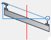
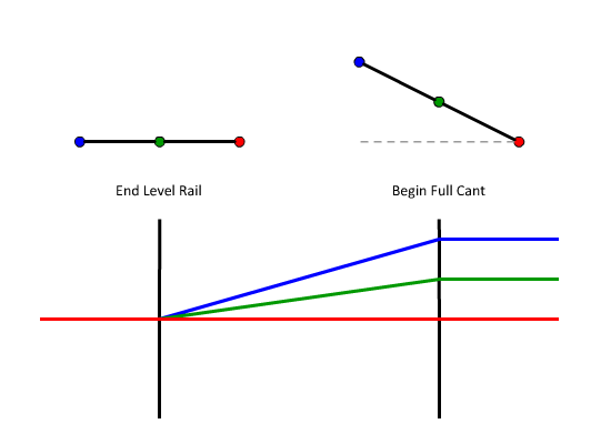
Outside rail — the rail farther from the curve centre. On a left turn this is the right rail. The plane rotates around the outer rail; the inner rail “falls” by the cant.
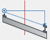
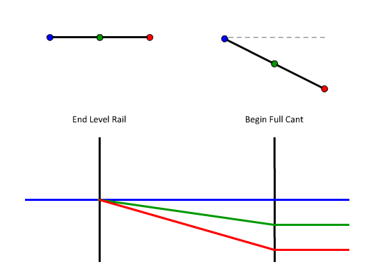
Center / Left rail / Right rail — alternative pivot points accepted on import (LandXML, ICAD .iqz). Less common; the calculator treats them with the same theta / rotation-point geometry described in Rail alignment — cant, CTC and UTC.
The active rotation point feeds into the engine’s CalcTheta and
GetRotationPointX functions, which are called from
SetoutRail whenever Mode = Rail is selected.