2.5.7.3. Rail alignment — cant, CTC and UTC
Rail-alignment calculations differ from road centreline calculations because the track plane is tilted by the superelevation (cant) applied between the two rails. Standard road setout uses the horizontal X/Y plane and stamps Z on at the end; rail setout has to know on which rail the plane pivots, how much it tilts, and which direction it tilts in.
Rail mode is enabled per alignment by the IsRail flag (Tools ▸ Options ▸ Rail). When set, the Cant cross-section collection becomes editable and the unified Setout/Measure dialog enables Mode = Rail.
2.5.7.3.1. Coordinate systems used
There are two coordinate systems on a cross-section plane:
UTC — Untilted Coordinate system. The horizontal, world-plane
section. X is the offset from the alignment centreline (positive
= right of travel); Y is the vertical height above the
alignment elevation. This is the system you would measure with a
total station: a level ruler perpendicular to the rails.
CTC — Cant-Tilted Coordinate system. The same section rotated
by the cant angle θ around the rotation point. X is the
offset measured along the rail plane; Y is the height
perpendicular to the rail plane. This is the system rail engineers
work in when designing rolling-stock clearance — what you would
measure if your ruler tilted with the rails.
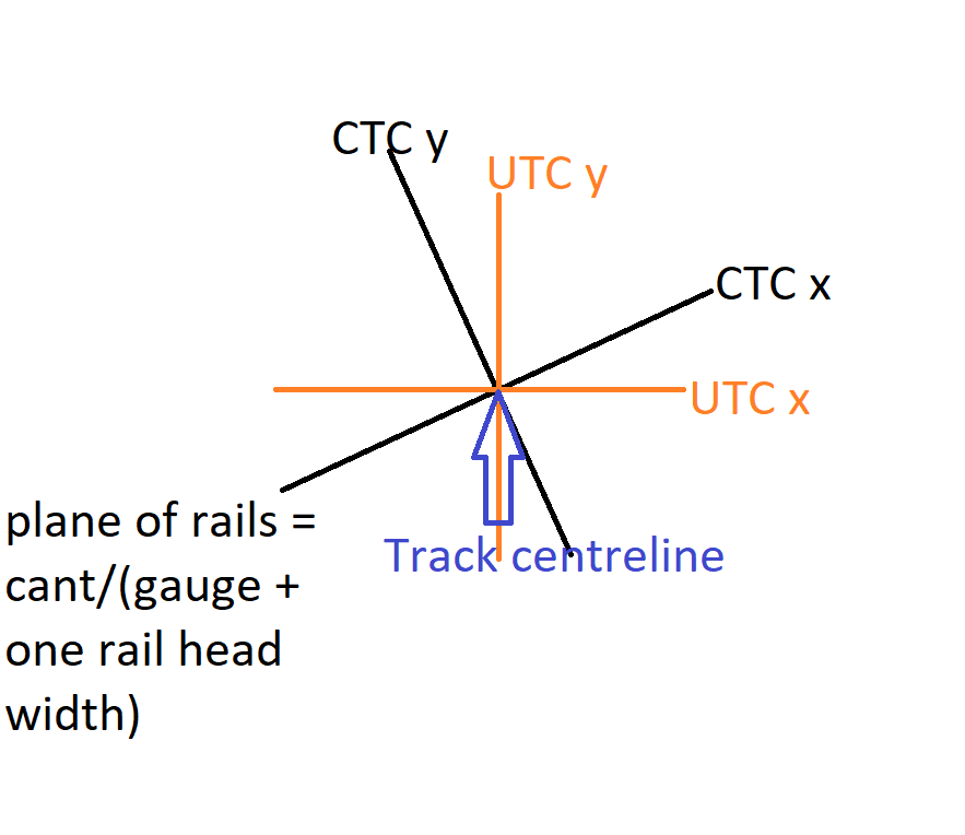
The two systems share an origin (the rotation point). They are
related by a rigid rotation by θ around that origin.
2.5.7.3.2. The rotation angle θ
Given cant c (centimetres) and gauge G (metres), the cant
angle is the arctangent of the rise over the gauge:
The sign depends on which way the track tilts, which depends on the turn direction and the rotation point:
Rotation point |
Turn |
Sign of θ |
|---|---|---|
Inside rail |
Left |
|
Inside rail |
Right |
|
Outside rail |
Left |
|
Outside rail |
Right |
|
Center rotation is symmetric — both rails move equally up and
down — so the section plane rotates about its midpoint and the
left/right sign distinction collapses; the engine still applies
the same ±arctan((c/100)/G) magnitude.
On a tangent (Turn = Straight) θ = 0 regardless of any cant
value — cant only physically tilts the plane where there is a
curve.
2.5.7.3.3. The rotation-point X coordinate
The rotation point is one of the rails or the centreline, expressed as the X coordinate in the section plane (Y is always 0):
Rotation point |
Turn |
Rotation point X |
|---|---|---|
Inside rail |
Left |
|
Inside rail |
Right |
|
Outside rail |
Left |
|
Outside rail |
Right |
|
Center |
any |
|
2.5.7.3.4. CTC ↔ UTC conversion
Given a CTC point (x_c, y_c) and the rotation point
(R_x, 0), the UTC point is the CTC rotated by θ around the
rotation point:
(The +0 makes the rotation-point Y explicit; we always pivot about the rail plane so the rotation point’s height is zero.)
The inverse (UTC → CTC):
2.5.7.3.5. Putting it all together — SetoutRail
When the user requests SetoutRail(Station, CTCOffset, CTCDh):
Base setout — get the centreline point and bearing at
Station:Result := Setout(Station, 0, 0).Cant lookup — read
cantValfrom the Cant collection at the continuous (pre-equation) chainage ofStation.Geometry — compute
\[ \begin{align}\begin{aligned}\theta = \text{CalcTheta}(c,\,G,\,\text{turn},\,\text{rotPt})\\R_x = \text{GetRotationPointX}(G,\,\text{turn},\,\text{rotPt})\end{aligned}\end{align} \]On a tangent
turn = tdStraight→θ = 0andR_x = 0; the conversion is the identity.CTC point —
ctcPt := (CTCOffset, CTCDh, 0).UTC point — apply the CTC → UTC rotation around
(R_x, 0, 0)(see formulas above). The resultutcPtis the horizontal offset and vertical height of the desired point on the world plane.World X / Y — call
OffsetPointAtStation(Station, −utcPt.X)to project the horizontal offset along the alignment perpendicular. The negation matches the project-wide right-positive offset convention (OffsetPointAtStationuses a left-normal internally;SetoutandSetoutOffsetapply the same negation).Point height —
PointHeight := Elevation + utcPt.Y, whereElevationis the alignment elevation atStation.Result fields — also write back
Theta,Cant,Gauge,RotationPoint,CTCPoint,UTCPointto the result record so consumers (the on-window rail-details panel, the rail-detailed report, batch setout) don’t have to query anything else.
Note
The legacy version of the code had a local “swap” inside
SetoutRail that flipped tdLeft ↔ tdRight before calling
CalcTheta / GetRotationPointX, on the assumption that
those functions were tuned to an old inverted turn-direction
convention. That swap inverted both the theta sign and the
rotation-point X. Reference comparisons against published metro
data exposed the inversion; the swap has been removed
(CalcTheta is correct for the new convention). The current
release matches the canonical CCW-positive turn convention.
2.5.7.3.6. Rail-detailed report
When Add to Results is pressed with Mode = Rail (or when Batch Setout runs with Mode = Rail), the engine emits the detailed rail report — 16 columns:
Chainage   Distance-CTC   DH-CTC   Distance-UTC   DH-UTC
           X           Y           H           H align
           Cant(cm)    Cant Point   CantPt X   CantPt Y
           Turn        Theta(rad)   Gauge(m)
Sample run on an alignment with cant = 1.250 cm, gauge = 1.500 m, inside rail rotation, left turn, at chainage 11+100, CTC offset = 1.000 m, CTC Dh = 0:
 Chainage    Distance-CTC    DH-CTC   Distance-UTC    DH-UTC          X          Y       H    H align   Cant(cm)   Cant Point   CantPt X   CantPt Y   Turn   Theta(rad)   Gauge(m)
11100.000           1.000     0.000          0.983     0.015   101754.883   104707.720   134.380  134.365     1.250   insideRail     -0.750      0.000   Left       0.0083      1.500
What each column means:
Column |
Meaning |
Chainage |
Displayed station |
Distance-CTC |
CTC offset (input — measured in the tilted plane) |
DH-CTC |
CTC height difference (input — in tilted plane) |
Distance-UTC |
UTC offset (horizontal-plane projection of CTC) |
DH-UTC |
UTC height (vertical height above alignment) |
X |
World easting at this point |
Y |
World northing |
H |
Point elevation (= alignment elevation + UTC DH) |
H align |
Alignment elevation at chainage (no offset/cant) |
Cant(cm) |
Cant value at this chainage |
Cant Point |
Rotation point label ( |
CantPt X / Y |
Rotation-point coordinates in the section (Y = 0) |
Turn |
Straight / Left / Right at this station |
Theta(rad) |
Cant rotation angle (signed) |
Gauge(m) |
Active gauge |
The same fields appear in the dialog’s inline Rail Details panel when Mode = Rail is selected. So you can verify a row before committing it to the Results page.
2.5.7.3.7. Cant ascii file
The Cant collection round-trips as a simple chainage / value segment list — same shape as the other cross-section collections:
chainage_1, cant_start_cm, chainage_2, cant_end_cm
chainage_2, cant_start_cm, chainage_3, cant_end_cm
...
Comma-separated, one segment per line.